
Making blog

I finished painting weights on the entire turtle tonight so now it won't move weirdly.
What I mean by move weirdly is that if you look at the plain photo of the arm, it's not bending properly. That's because the software is just guessing how it will move. Because of that, artists have to go in and fix that, or in other words repaint what the software guessed. In the similar screenshot of this image, you should see a black and white gradient. That's the paint that has to be fixed.
In the last picture, that's how the paint should look like for the turtle to move properly. But not all 3D models will have weights painted like that. Different objects move different ways, but because the turtle is a machine, it's shape doesn't change. In comparison to a human arm, there would be a gradient because a human's skin folds and stretches when it moves.
Now that this part is finished, I will be moving on to the animating process :D

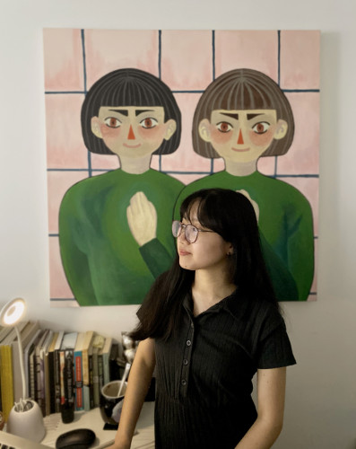
About 2 weeks ago, I was given the opportunity to finally get to meet and talk to my little inventor behind this wonderful invention idea, Lily-Ane! :D It was really nice to get to know and talk to her as well as get her feedback on what she thinks about the project so far! I also, had the pleasure to meet her teacher as well! I'm really happy that Lily-Ane seems happy with the progress of the project so far! Yay! :D We also, discussed about things she would like to add to the project too such as sounds! Also, I'm glad the meeting went well despite how nervous I was and the fact that I needed a translator to communicate to Lily-Ane since I couldn't speak and understand French fluently. So I'm really thankful that José was there to help with translating the conversation between me and Lily-Ane! As well, as thanks to Phoebe for arranging the zoom call! Overall, I’m excited to continue working on bringing this invention to life! :D
For the past few weeks, I’ve been working on the storyboard through sketching it in Photoshop on a storyboard template and finding ways to best showcase the functionality of the invention. I decided that the best way to show this is by showing how the invention cleans the ocean based on how I interpreted Lily-Ane’s description of how it functions so far as well as having the invention be subtly surrounded by other living ocean habitants to show that the invention is considerate and friendly to the inhabitants living in the environment. . After getting some feedback and re-doing the storyboard a few times, I’m currently satisfied with the version I have right now and I’m excited to move on to the next step of this project! :D
A bit random but to help me understand the invention a bit better, I decided to make a mini model of one of the rough designs using clay, sticky notes, and a paper clip. I wish I had more clay colours on hand especially white and black so I could’ve added the distinct stripes and facial expression on the invention’s design. Though otherwise, I had fun making it!
Picking up from the last time, I managed to come up with two design ideas for the invention based on Lily-Ane’s drawing of the invention and references! Yay! Honestly, both designs are really similar to each other with the main differences is that one is rounder to portray a more friendlier approach, and the other one is more slim and longer as a reference to what some submarines look like in real life. Personally, I like the rounder design best. So I decided to explore it a bit more through some sketches while incorporating the functionality of the invention in mind as a placeholder for the final design. Since I wanted to get Lily-Ane's feedback on which design she likes best before finalizing it. I also, decided to explore a different color variation since from looking at some clown fish references, their colours vary between yellow-orange and dark orange.
As a starting point for most projects especially with this one, I like to gather and look at different references just to make sure I understand how things actually look like and sketch them. I do this because sometimes (at least for me), when I think I know what something looks like by memory, I tend to be proven wrong in the end when I search the pictures of the actual thing in question as I never realize that there are a lot of details that can be overlooked when remembering from memory. As well, references can also, help with inspiring different ideas so it’s really helpful!
With, Lily-Ane’s drawing of her invention in mind as well as a starting point, I started looking for references that bear similarities to the invention in hopes to understand not only the invention better but also, to explore and find ways to convey the invention as great as possible! I started looking at references for the clown fish and angler fish specifically because her invention’s design makes me think it’s a hybrid of the two. Though from looking at these references, I learned that angler fish are actually really scary looking in real-life! I also, looked at different submarine references such as real ones and the ones depicted in children’s media just to see the similarities and differences. Ultimately, these references will help me figure out how I would approach the design of this invention.
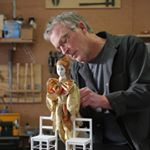
Hi, David Dumbrell here. When I looked over the inventions I was drawn to Ericas idea, she had tackled the problem of how to deal with the plastics once recovered from the ocean.
I zoomed with Erica a short time later to discuss her invention and we went over my drawing of her invention ”Plastic Masterpiece Maker”. My drawing shows an industrial plant with a conveyor belt running from one machine to the next. Erica agreed and had a few thoughts about what colours she would like to see, she gave the go ahead and work began to bring her invention to life.
The first thing I like to make is the structure that holds the moving parts, then the gears that will drive each drive shaft. Mounted on each drive shaft ( there are 3) is an cylinder with small spikes, the spikes are added to make sure the belts do not slip.
I used seat belt material for the belts. The belts come from the base up through the top and onto rollers that I have covered with an old bike inner tube so the belts don’t slip.
Now that the basic structure is made I can now move on to the real fun part, making all the machines that make up Erica’s invention.

The water containing waste material gets into the vessel by way of the vacuum pick-ups, then underneath the control room and finally into the section at the back of the vessel. In that section the water enters a net which collects the big and small particles and the purified water exits the vessel through the water exhaust manifold (refer to Ava’s drawing). To design the manifold with its artistic curves, as previously mentioned, I had to master the “sculpting” function in Fusion 360. After watching a couple of YouTube videos it was fun to pull and stretch the various faces of a starting cube to form the desired shape (see the drawing), a bit like playing with Play-Doh. For the net used to store the waste, I used material from a discarded window screen (thanks to the local squirrels) that I sewed into the required shape. I also made the access port with its decorative rivets on the 3D printer. I dipped the as-printed PLA piece on the flat printer bed in very hot water for 20 seconds and bent it to the right curved shape.
(English version below).
J’ai bien aimé l’idée de Simon de propulser la navire avec un roue à aubes. Cela me faisait pensé aux bateaux qui naviguaient le Mississippi il y a plus d’un siècle. Comme le modèle a déjà 37cm de long, afin d’éviter de le rallonger encore plus, j’ai décidé d’inclure deux roues à aubes disposées de chaque côté de la coque au lieu d’une seule roue à l’arrière. J’ai fabriqué les deux roues sur l’imprimante 3D de même que le support pour le moteur miniature. J’ai utilisé deux engrenures de ma collection pour connecter le moteur à l’arbre d’entraînement. Voir le vidéo clip qui montre les roues en action.
(Version française plus haut).
I liked Simon’s idea of a paddle wheel to power to boat. It reminded me of the river boats navigating the Mississippi river in the old days. Since the model is 37cm long already, I chose to use two paddle wheels instead on one and locate them on both sides of the vessel instead of at the back. I made the two wheels on the 3D printer as well as the bracket and support for the miniature gearmotor. I used two gears from my collection of discarded parts to connect the motor to the driving shaft. The paddle wheels came to life in the attached video.
For the two arms extending in front of the vessel that will suck the water in to filter plastic waste, I used two small Lego bricks. I drilled holes through the stubs, made backing plates on the 3D printer and join brick, plate and plastic tube together with epoxy glue.
(English version below).
Pour la courroie du convoyeur, j’ai découpé une bande en caoutchouc d’une vieille chambre à air et collé les deux extrémités avec de la colle à caoutchouc. Après quelques heures entre les machoires d’un serre, la courroie s’est avérée très robuste. J’ai ensuite fabriqué deux petites poulies sur l’imprimante 3D et sélectionné une petite courroie d’entraînement de ma collection de pièces recyclées. Après quelques ajustements, le couple scooper-convoyeur est maintenant fonctionnel ! Voir le vidéo clip ci-joint.
(Version française plus haut).
For the conveyor belt I cut a strip of rubber from a discarded inner tube and joined the ends together using rubber cement and a good clamp. The result was a pretty strong belt. I made two pulleys on the 3D printer and selected the right size belt from my collection of recycled parts. After a few adjustments, I got the scooper-conveyor combination to work nicely ! See the attached video.
This weekend, I've been rigging the turtle. If you look at the picture of the turtle made up of blue lines (we call this the wireframe), there are colourful shapes on the inside. Those are the bones and joints that tell the turtle model how to move. But we can't move the bones and joints by themselves since the software will get confused. So the next step of rigging after making the skeleton is creating the controllers.
In the next picture with the four different views, you'll see circles around the different parts of the model. Those are the controllers. The controllers help prevent the software from getting confused and making the turtle move weirdly. They also help me move the turtle faster since I don't have to click on every individual part to move it.
This week I'll finish rigging the Turtle Camera Claw. I have to do the final step which is painting weights, which is something I'll talk about next blog post when the process is finished :)
After doing the concept art and figuring out the general colour scheme of the animation, I started doing the rough outlines of my storyboard! Nothing in the storyboard is final and knowing that I don't have to stick to it allowed me to play around with the placement of the frames.
(English version below).
Le coeur de l’invention de Simon est le scooper. Tel que mentionné précédemment, j’ai créé une combinaison scooper-convoyeur. Pour le convoyeur j’ai fabriqué des pièces sur l’imprimante 3D (rouleaux, supports des rouleaux, ancrage du moteur) et utilisé deux engrenures de ma collection de pièces recyclées, de même qu’un petit moteur miniature CC avec engrenage intégré. Le vidéo clip montre le premier test effectué avec succès.
(Version française plus haut).
The heart of Simon’s invention is the scooper. As explained before I implemented the idea in the model using a combination scooper-conveyor. For the conveyor I made a few of the parts on the 3D printer (rollers, brackets, motor retaining ring) and used two gears for my junk pile as well as a small miniature gear motor. The video shows the first successful test of the roller driving the mechanism.
I liked Ava’s idea of using some sort of magnet to capture metal debris from the ocean water. With the objective of putting some animation into the model, I decided to push this idea a bit further and therefore include a small electromagnet. To do so, I repurposed a small actuator that I had in my junk pile (it probably came from a recycled printer). I extracted the coil and used two nails that I shaped and cut in such a way to reproduce the shape shown in Ava’s drawing. By turning the coil current ON and OFF, I am able to turn the magnetic field ON and OFF as shown in the attached video.
(English version below).
Armé d’un bon design, j’ai donc fabriqué la coque du navire sur l’imprimante 3D. Le navire mesurera 37cm de long alors que mon imprimante Prusa a une capacité maximum de 25cm. Aucun problème: sur l’ordinateur j’ai simplement « coupé » la coque en deux parties sur le large. C’est en fait la façon dont les vrais navires sont construits, soit par morceaux qui sont soudés ensemble. Pour ma part j’ai utilisé de la colle époxyde pour relier les deux moitiés ensemble et j’ai renforci le tout à l’intérieur de la carlingue en ajoutant une deuxième couche armée de fibre de verre. Ceci garantira la solidité du navire en haute mer…
(Version française plus haut).
Now that the design looks under control, I first printed the hull of the ship on my 3D printer. The ship will measure 37cm in length while the capacity of my Prusa printer is only 25cm. No problem: I simply “cut” the hull in two pieces on the computer and printed the pieces separately. In fact this is how real ships are built: in pieces that are then welded together. In my case I simply used epoxy glue to join them; I used a second coat reinforced with fiberglass to ensure a strong hull. Things can get rough on the high seas…
I did the design of the control room on Fusion 360 then fabricated the parts (desk, side panel, floor, pilot chair, ring for the partition to the back of the ship) on the 3D printer.
I cut the front window and the back partition out of acrylic (Plexiglas) using a scroll saw equipped with a blade made for cutting plastic. With the current COVID situation Plexiglas is hard to find in stores nowadays but luckily I had some leftover in stock from previous projects.
I then put things together temporarily to check the fit with the main vessel (a.k.a. soda bottle) and it matched nicely. I will remove the white protective sheet on the clear acrylic plastic later in order to avoid scratching the pieces while doing the rest of the project.
(English version below).
Après une bonne période d’incubation et échange d’idées avec ma fille Isabel qui est également dans l’équipe des « makers », le gros de la conception est maintenant terminé. Je suis relativement satisfait du couple scooper-convoyeur (voir croquis original et design 3D). J’ai déjà commencé à fabriquer les pièces sur l’imprimante 3D. Les choses commencent à rouler…
(Version française plus haut).
After some brainstorming, including with my daughter and fellow maker Isabel, much of the design work is now complete. I am happy with my rendition of the scooper-conveyor idea (see a first sketch and the 3D design). I have already started to put my 3D printer to work. The ball is rolling…
Today I had my first conference call with Ava, the Little Inventor of the Cleaner Picker Upper. It was great to finally get to meet her in person (well, virtually anyhow…) and exchange ideas with her. Her teacher, Mr. Ashley and Jill Bennison of Little Inventors were there to facilitate the call. Ava seemed pretty happy with my rendition of her original idea (so far anyway). When I asked Ava about other ideas that came to her mind when she was creating the original concept of the CPU, she did mention that the idea of propelling the vessel with a kind of “whale tail” instead of a conventional propeller had crossed her mind. I found this idea quite interesting. I remember reading in some scientific magazine or journal that the swimming motion is one of the most efficient way (less energy consumption) to move an object (fish, underwater vessel, etc.) in water. On one hand I am happy that she chose to use a propeller since it was easier to make a model, although I must admit that she triggered my curiosity. I might revisit this idea on a future project. I also told her that making a model of her invention had forced me to develop new maker skills, particularly in the area of “sculpting” artistic shapes in 3D on the computer. As a matter of fact I subsequently applied this newly acquired skill to the other project I am working on (ref.: the Clean Machine). Thanks Ava !
I've been brainstorming ideas to bring The Termanater to life! On the top of my list are colour and form. I thought the main machine should be visible even from afar which made me think of bright colours while the drones should correspond with the colours of their environment. I also added a solar panel on top of the main body so it would get its energy from the sun while simultaneously storing power for when it gets dark or rainy.