Making blog

Hi, Spencer Barclay here. This week is an exciting one, as the Space Home project is really coming together, literally.
Once I had one fully detailed and painted Space Home that I was happy with, I duplicated all of my designs in Adobe Illustrator and sent them to the laser cutter. I organized all of the pieces on my workbench, I had made my own giant model kit! I assembled and detailed all of the other 4 Space Homes, carefully securing the copper fittings to the inside of the boxes, so the structure would be as strong as possible.
When I was finished the assembly, the copper fittings were kind of heavy altogether, so I turned to my colleagues at Our Home and Miniature Land to help me create a structure to support the finished miniature. To create the appearance of a floating space installation, the Space Homes miniature needed to be supported from the back, so a bendable plywood was used to give enough structure with the least amount of material. I spray-painted a space background, complete with stars and pink nebulas. Now I had a display base that added structure, and a wow factor.
A quick detail that appears in the video with no explanation is the 'Canadarm' grabber claw. I needed to find a toy or something that had ball joints or articulation, so I could create something similar. I went to the dollar store and there was a wooden artist's sketching figure that had all of the joints articulated and it was only $4! I pulled off one of the legs, lengthened it with some plastic tubing, and with some various details and paint, we have our very own miniature Canadarm.
William's original Space Homes drawing includes the Earth, so I wanted to make sure it was in the final model. I turned to my colleagues again to help me create a curved platform at the bottom of the display structure. I printed a real photo of the Earth from space and glued it to the surface of the curved platform. It looks awesome and gives the Space Home miniature some context while it is displayed.

Step three : 3D model design also known as CAD (computer assisted design). The aluminum tube and the mirror that you saw in the previous post are now modeled in the software at the right scale. Each white parts in the picture are designed to fit the purchased components and are going to be 3D printed.

Step two is to purchase the required components to fit the idea of Amy's Personnel Canadarm. I can now precisely measure each components to fit everything perfectly with the 3D print that will come at the next step.

First, I draw a design concept to have a clear plan of what I will need to do. I now know what I need to model on a 3D design software, what I have to 3D print and what I need to buy. I am also able to approximate a few deadlines for myself.

MArSBot was my first project that combined Arduino, Python and Artificial Intelligence (AI). Life on the International Space Station can be hard for Astronauts as they are away from their families and kids. My MArSBot scans the faces of Astronaut on the International Space Station and uses AI algorithm to see if anyone is feeling sad. It then gives them a high five!
It took me several weeks to make. As with all projects I like to make a drawing using paper and pencil. I then start to think of materials I will use to make my project and the programming I need to do to make my robot move. The project is now complete. It is one of my big projects and I am very happy with it. But I want to improve this project so that the Bot will be able to smell its surroundings and be able to say if a flower smells good or not.

I tested it many times and made changes to the code in Arduino and Python. It took me lots of attempts to transmit correct information from Python to Arduino. I found out that you have to close the python console before you upload the Arduino code as both use the same COM port. Next time I need to learn how to create a separate COM Port for 2 projects using the same computer.

I had to place the horns of the servo at the right place because they can only go 180 degrees (half a circle). They had to be aligned so that the robot's hands and the robot's face displayed the correct movements depending on the happy or sad emotions detected by the robot. Both the arms also had to go up the same height. So I had to do lots of adjustments in the code. As there were lots of servos to control, the code became really long but then I learned about naming the servos creatively which made it easier to remember them.

I had to decide where I will attach the head and the arms. I had to make changes in the wiring to make all 6 servos work. As the servos require a lot of power, I had to attach an external 6 volts power supply to the servos.

I sourced the help of my good friend Jade from @_kiwitography_ to take photos of the constructed and deconstructed spacesuit - Fuzz and all!
Finally I created an overview of this project using Adobe InDesign to make two 11” x 17” posters that explain the sculpture.
Last step is carefully package this GLASS sculpture for shipping. Post to follow.

Hi, Spencer Barclay here, it's been a busy week taking the Space Homes project from a detailed drawing and making it into a 3D structure.
I prepped a lot of materials to share with William during our Skype chat, he was able to see a 2D mockup, a detailed drawing, and a 3D mockup of a single Space Home. William seemed really happy, so I knew that I could move forward.
I started adding to the 3D mockup, I had a lot of fun designing 'Sci-Fi' panels that create the surface texture of the Space Homes project, the laser cutter was incredibly helpful in bringing those details to life. I worked to finish one Space Home, fully assembled, with all of the details included, and a coat of white primer. Then I would know exactly how it was going to look before I built 4 more!
I also went to the hardware store to find materials that would make up the tubes running between the Space Homes. Something that was structural and had some interesting surface texture, and I found it. Copper couplings and electrical tubing fit together perfectly, they were well priced and looked great without much additional work.

Hi, Spencer Barclay here, I'm a freelance model builder working with Our Home Miniature Land (OHML), an entertainment destination featuring a miniature of Canada, set to open in 2020.
I looked at William's Space Homes illustration carefully, noting all of the details, and started to think about what size of miniature seemed most appropriate. I chose the scale we use at OHML, 1:87 scale, also known at HO Scale. This meant there'd be lots of readymade options for me to modify to include in my miniature, especially the interior, where there'd be things like figures, couches, steps, windows and doors.
To prepare for our Skype conversation, I created a 2D mockup that was very close to William's drawing, so I'd be able to fully understand how large the overall miniature would be. After that I created a 3D cube of one of the space homes. Then I created my own drawing showing some of the additional details I'd be adding, like surface textures and solar panels.
I had lots to show during our chat, which made it easy for William to provide feedback and help me decide on my next steps.
It will be safer to power the star not from one discrete output, but for each LED separately.
I spent so much energy on writing a program to perform parallel tasks on arduino, and because of a bad servomotor, the microcontroller is unable to cope with the load. But it's okay I'll take another arduino and everything will work as it should.

Creating the helmet of the PJ Dress Up Spacesuit is done in the same way as the bottom portion (legs) in the hot glass studio through blowing and careful torch assembly of components. One big difference is that I have placed the colored layer on the OUTSIDE of this shape rather than the interior which is more common. This is done so I can SANDBLAST (form of COLD WORKING - processes done to glass when it is hard and room temperature) through the colour and leave a clear layer intact to behave as window for the astronaut to see the universe and us to see inside too!
In order to SANDBLAST only the desired area I used sticky vinyl resist to protect the areas that I wish to remain shiny and untouched. I also use the Sandblaster and DREMEL to carve arm holes into the helmet.
Making the suit in two parts was a fun challenge - matching the diameter of each part so that suit appear cohesive is an interesting task. The process is done hot so you cannot simply pause and measure with numbers. Glassblowers usually use calipers to get a rough measurement and the rest is achieved with experience and by eye.
I tried making the pants for this project 3 times, first in clear to work though the process. The first try was too messy and wide (and CLEAR), I found my second try too dark in colour, tall and long. Making a project more than once is very NORMAL in glassblowing. The helmet was more simple and took one attempt! WOO!
Now I need to check the performance of the pulse sensor

Glassblowing is often done in teams, with the help of my assistants I can blow and sculpt the shape of pants, coloured by a dense chuck at the core of my initial gather. This chuck is called COLOUR BAR and is used to achieve bold uniform layers of colour in glass. The tail is served as a hot blob and snipped with steal shears into shape. Next all spikes and feet are taken from pre heating kiln one by one to be fused into place with the power of a oxygen torch! (Like welding!) This process takes about 45 minutes! When shaping is complete we remove the sculpture from the blowpipe using temperature shock and pop it the cooling kiln (ANNEALER) to cool slowly over night. Again, once the sculpture is cooled I can use a wet DIAMOND saw to cut off sharp and unwanted material. Next step is to create the helmet in a smiliar way!
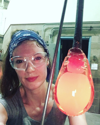
When glass is hot the colours appear very different than at room temperature. This can be confusing and fun... check out how green the glass looks on the blowpipe compared to its bluish tone when cool on the table.

Complex glass sculptures can be made in parts. To begin I prepare the detailed aspects of the suit for later attachment to the main sculpture. By rolling clear molten glass in FRIT ( crushed, coloured glass chucks - like big sprinkles!) I can form purple and teal spikes and feet. After melting in the FRIT I shape the hot glass with my graphite paddle and steal glassblowing tools. This is all done on a long metal rod that acts like a handle so I can heat the glass without getting too close! At the end of my sculpting process I cut my piece off the rod by using temperature shock and pop it into a 1000 degree F. oven to cool overnight slowly. The next day I can grind and flatten any sharp spots with DIAMOND wheels to create finished and smooth edges from where the glass broke off the pipe.

Hand stitched and embroidered a character of David St. Jacques to fit inside and wear the Dress Up Suit. Can you see the resemblance? Time to fabricate in the hot glass studio...

While I was working this week, I made sure to print all the pieces I needed for the final version. I needed to reprint the base, because my first design was too small to accommodate the big selector knob, and I needed to reprint the sides of the cube, because they weren't perfectly square, which left a bit of a gap at the top of the cube. Finally, today, I was able to assemble all these new parts and give it all a test run. I'm pretty happy with how it's shaping up! You can see a few pictures of the different colors below, and a video of the suncube going through a demo cycle, which simulates sunrise, daytime, sunset and nighttime within a 2 minute period. I also tested a the 90 minute ISS cycle while watching a TV show, and, I'll leave the cube running overnight and tomorrow to test out a full 24h Earth cycle.
